-
Phone
86-13280716328
-
Address
Fuzhou Road No. 37, Pingdu City, Shandong Province, Qingdao, Shandong, China
-
E-mail
LatestProducts


Hydraulic Control Valve Pressure Reducing Valve
China Hydraulic Control Valve Pressure Reducing Valve, Find details about China Pressure Reducing Valve, Adjustable Pressure Reducing Valve from Hydraulic Control Valve Pressure Reducing Valve - Qingdao Judibode Trading Co., Ltd.
Description
Basic Info
- Model NO.: DN40 to DN1000
- Temperature: Low Temperature
- Valve Seat: Single-Seat
- Material: Ductile Iron
- Trademark: judibode
- Specification: DN40 to DN1000
- HS Code: 8481804090
- Certification: SGS, CE
- Connection: Flange
- Structure: Lever
- Hydraulic Control Valve: Pressure Reducing Valve
- Transport Package: by Plywood Box
- Origin: China
Product Description
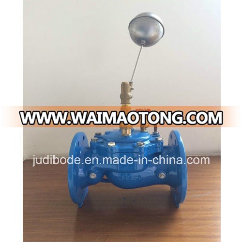
hydraulic control valve pressure reducing valve
1. 1. Product introduction
This valve is designed and manufactured by our company according to the advanced product of the same type in the United States, France and China. The valve body adopts the streamlined design with less internal head loss and large flow. The transmission mode adopts the hydraulic operation, and the pipeline pressure is used to automatically control the up and down movement of valve disc, control the valve opening, and adjust the downstream pressure, so as to maintain the downstream pressure above the pilot valve spring set value. When the downstream pressure exceeds the set value, the valve will shut down automatically, and guarantee the constant outlet pressure.
The product is the ideal product used for domestic water, fire system and water supply system.
2. Structural
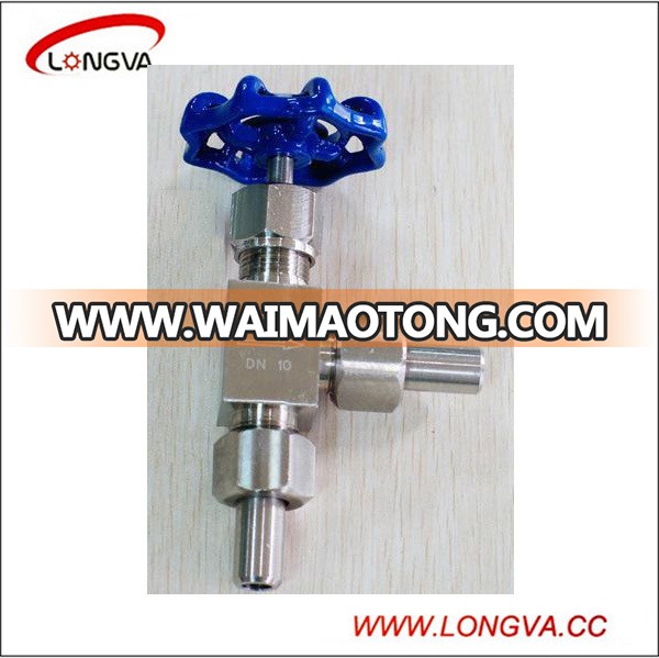
The valve consists of the main valve, pilot valve, needle valve, ball valve, micro filter and pressure gauge etc. The pilot valve, needle valve, ball valve and pressure gauge are connected to the main valve with pipe, so it is collectively called as the pipe control system, as shown in the below picture.

1. Needle valve; 2. Pressure reducing valve; 3. Ball valve
3. Main specification
5. Working principle and purpose
The pressure P1 enters the control room of main valve through pipe and needle valve 23 (see the chart), and establishes the downward pressure P3. The outlet pressure P2 can act on the diaphragm of pilot valve 22 through the pipe and conflict with the adjustment spring of pilot valve. When the downstream pressure exceeds the pilot valve spring set value, the pilot valve will be closed, the water discharge in the control chamber is 0, and the variable pressure F3 reaches the maximum value, and the main valve pressure seat valve is closed tightly. When the downstream pressure is less than the pilot valve spring set value, the pilot valve will open, and the water discharge in the control chamber will pass downstream through the pilot valve 22 and ball valve 19. The needle valve opening is small (1/4-1/2), and the inlet duct is smaller than the outlet duct in the diameter, so the discharge speed is greater than the inlet pressure filling speed, thus the pressure F3 in the control room is reduced, and the inlet pressure P1 acts on main valve disc 23 and raises it, so as to open the decompression valve. In the steady regulation state, the discharge flow is equal to the filling flow, the main valve opening is unchanged, and the downstream pressure is stable.
6. Installation and adjustment
1. The optimal installation of main valve is horizontal installation with pump cover up. Other installation methods can also realize the use function, and it is necessary to thoroughly remove the sundries in the pipe before installation. Pay attention to the flow direction arrow on the main valve body, and follow the correct direction. Ensure that no pipe stress is on the valve body and internal parts after installation.
2. Before the installation of main valve, a gate valve and a filter should be installed, and a gate valve should also be installed behind the main valve for repair.
3. Regularly clean the micro filter 24 on the main valve.
4. Thoroughly flush the pipe before filling water.
5. Install the bypass-valve for important water pipe
6. Pressure regulation method
1) Close the upstream isolation valve, open the downstream isolation valve for decompression, and lower the downstream pressure below 0.1MPa, and close the downstream isolation valve;
2) Rotate the pilot valve adjusting screw to the top position;
3) Open the upstream isolation valve slowly;
4) Tighten the pilot valve adjusting screw down, and the outlet pressure will gradually rise, and lock the adjusting screw until reaching the set value;
5) Under the excessive pressure regulation, adjust from the first step; that is, adjust from low to high pressure.

Installation drawing of 200X pressure reducing valve
1, 4, 5: resilient seat gate valve; 2. strainer; 3. 200X pressure reducing valve;
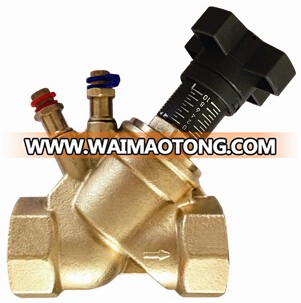
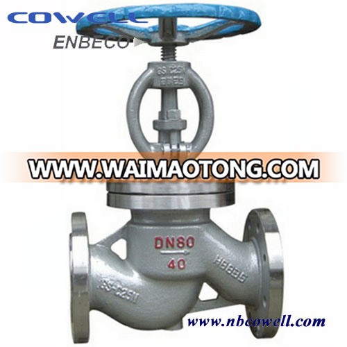
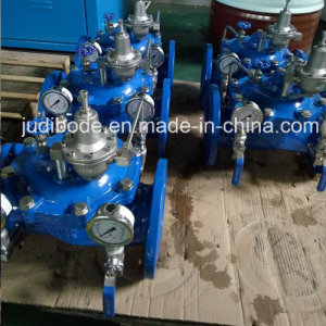
Our pressure reducing valve photo

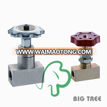
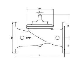
For the main part,we can supply three types
angle type
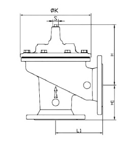
full bore type

reduced bore type
1. 1. Product introduction
This valve is designed and manufactured by our company according to the advanced product of the same type in the United States, France and China. The valve body adopts the streamlined design with less internal head loss and large flow. The transmission mode adopts the hydraulic operation, and the pipeline pressure is used to automatically control the up and down movement of valve disc, control the valve opening, and adjust the downstream pressure, so as to maintain the downstream pressure above the pilot valve spring set value. When the downstream pressure exceeds the set value, the valve will shut down automatically, and guarantee the constant outlet pressure.
The product is the ideal product used for domestic water, fire system and water supply system.
2. Structural
The valve consists of the main valve, pilot valve, needle valve, ball valve, micro filter and pressure gauge etc. The pilot valve, needle valve, ball valve and pressure gauge are connected to the main valve with pipe, so it is collectively called as the pipe control system, as shown in the below picture.
1. Needle valve; 2. Pressure reducing valve; 3. Ball valve
3. Main specification
| Nominal pressure PN | 1.0MPa | 1.6MPa | 2.5MPa |
| Shell-test pressure | 1.5MPa | 2.4MPa | 3.75MPa |
| Seal test pressure | 1.1MPa | 1.76MPa | 2.75MPa |
| Max inlet pressure | 1.0MPa | 1.6MPa | 2.5MPa |
| Adjustable range of outlet pressure | 0.09-0.8MPa | 0.10-1.2MPa | 0.15-1.6MPa |
| Applicable temperature | 0-80ºC | ||
| Applicable medium | Water |
The pressure P1 enters the control room of main valve through pipe and needle valve 23 (see the chart), and establishes the downward pressure P3. The outlet pressure P2 can act on the diaphragm of pilot valve 22 through the pipe and conflict with the adjustment spring of pilot valve. When the downstream pressure exceeds the pilot valve spring set value, the pilot valve will be closed, the water discharge in the control chamber is 0, and the variable pressure F3 reaches the maximum value, and the main valve pressure seat valve is closed tightly. When the downstream pressure is less than the pilot valve spring set value, the pilot valve will open, and the water discharge in the control chamber will pass downstream through the pilot valve 22 and ball valve 19. The needle valve opening is small (1/4-1/2), and the inlet duct is smaller than the outlet duct in the diameter, so the discharge speed is greater than the inlet pressure filling speed, thus the pressure F3 in the control room is reduced, and the inlet pressure P1 acts on main valve disc 23 and raises it, so as to open the decompression valve. In the steady regulation state, the discharge flow is equal to the filling flow, the main valve opening is unchanged, and the downstream pressure is stable.
6. Installation and adjustment
1. The optimal installation of main valve is horizontal installation with pump cover up. Other installation methods can also realize the use function, and it is necessary to thoroughly remove the sundries in the pipe before installation. Pay attention to the flow direction arrow on the main valve body, and follow the correct direction. Ensure that no pipe stress is on the valve body and internal parts after installation.
2. Before the installation of main valve, a gate valve and a filter should be installed, and a gate valve should also be installed behind the main valve for repair.
3. Regularly clean the micro filter 24 on the main valve.
4. Thoroughly flush the pipe before filling water.
5. Install the bypass-valve for important water pipe
6. Pressure regulation method
1) Close the upstream isolation valve, open the downstream isolation valve for decompression, and lower the downstream pressure below 0.1MPa, and close the downstream isolation valve;
2) Rotate the pilot valve adjusting screw to the top position;
3) Open the upstream isolation valve slowly;
4) Tighten the pilot valve adjusting screw down, and the outlet pressure will gradually rise, and lock the adjusting screw until reaching the set value;
5) Under the excessive pressure regulation, adjust from the first step; that is, adjust from low to high pressure.
Installation drawing of 200X pressure reducing valve
1, 4, 5: resilient seat gate valve; 2. strainer; 3. 200X pressure reducing valve;
Our pressure reducing valve photo
For the main part,we can supply three types
angle type
full bore type
reduced bore type